


LATEST NEWS

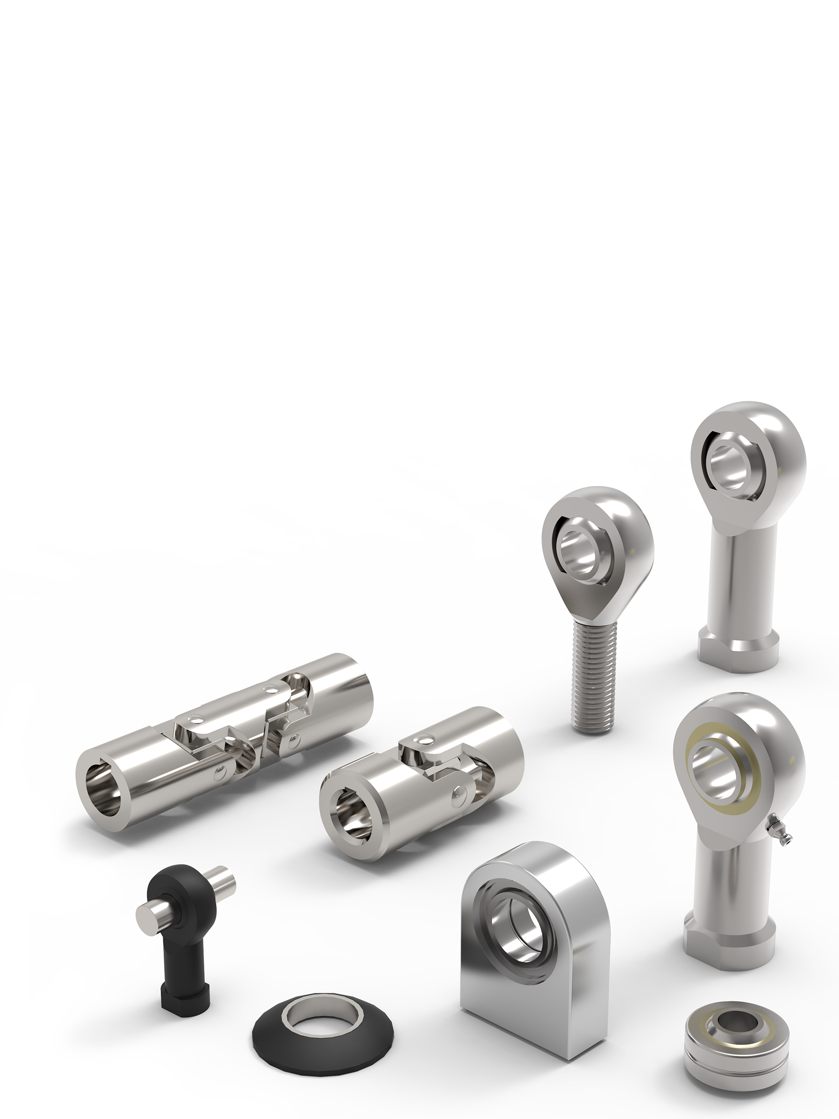
Precision Screws In-House Selection Have a closer look at our catalogue, showcasing our extensive range of in-house products. As a leading manufacturer in the industry, we are committed to providing high-quality solutions tailored to meet the diverse needs of our customers. Product Range...

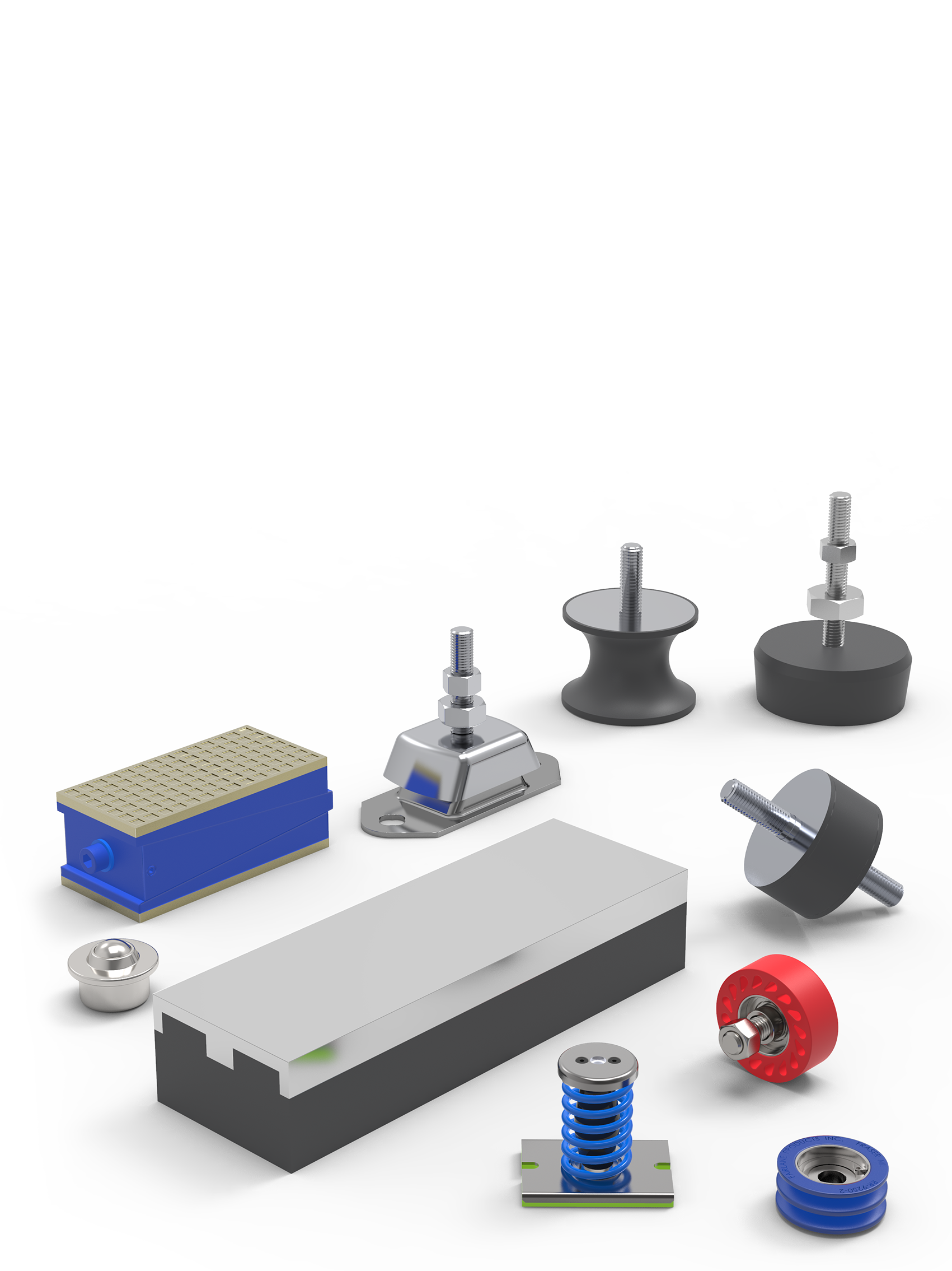
Defence Engineered: Ground, Sea & Air At Wixroyd & Automotion Components, we supply one of the UK’s broadest ranges of engineering components, supporting ground, sea, and air-based military manufacturing. From corrosion-resistant titanium screws to vibration-damping mounts and non-reflective...

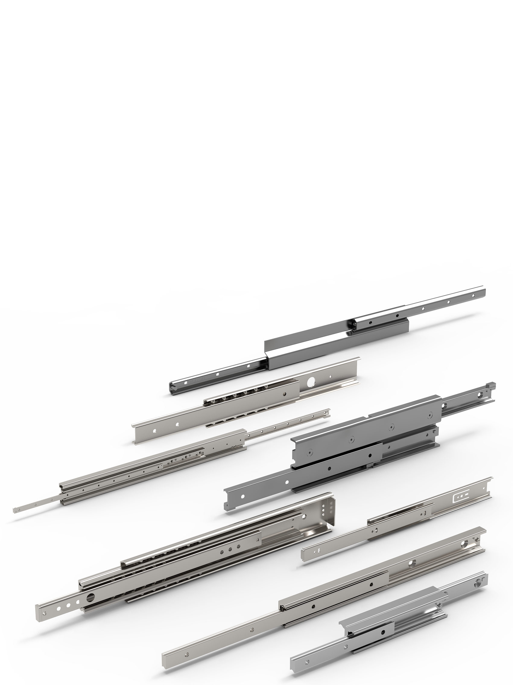
Discover What Automotion is All About Whether you’re mid-project or just speccing out your next design, having the right components and the right supply partner makes all the difference. At Automotion, we support design engineers with a wide range of ready-to-go components, backed by in-house...
More News


This content is not visible because of your cookie settings.
Alexia House, Glenmore Business Park
PO19 7BJ Chichester
United Kingdom
0333 207 4498
sales@automotioncomponents.co.uk
Route via Google Maps
Company registration no: 00496138
Company VAT number GB 408154022